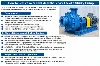
The pump shaft of a multistage centrifugal pump is equipped with two or more cascaded impellers. Compared with a single-stage centrifugal pump, it can achieve a higher head; compared with piston pumps, diaphragm pumps, and other reciprocating pumps, it can pump a larger flow rate. Multistage centrifugal pumps have higher efficiency and can meet the needs of high head and high flow rate conditions. In the petrochemical, chemical, power, construction, and fire protection industries, they have been widely applied. Due to their own particularity, compared with single-stage centrifugal pumps, multistage centrifugal pumps have different and higher technical requirements in design, use, and maintenance. Often, due to people's negligence in some details or insufficient consideration, multistage centrifugal pumps frequently experience abnormal wear, vibration, and shaft seizure after being put into use, resulting in shutdown. 1. Design aspects 1.1 Basic structure The common basic structures of multistage centrifugal pumps include horizontal split type and segmented type or called multistage series type. The structure of the horizontal split type is characterized by the upper and lower pump bodies being对接ed through the horizontal dividing surface of the axis center. The inlet and outlet pipes, part of the volute, and the flow passage are cast on the lower pump shell. Maintenance and repair are relatively convenient, and during maintenance, the upper shell of the pump can be removed directly without dismantling the pipeline of the pump. The structure of the segmented type is characterized by each stage consisting of a impeller located in the diffuser shell, and the diffuser is connected by bolts and connecting rods, and the stages are connected in series by fixed rods. The advantage is high pressure resistance and less leakage. However, during maintenance, the inlet pipeline must be disassembled, and the disassembly and assembly difficulty is relatively large. Generally, it is believed that the horizontal split type multistage pump has better stiffness and lower pump vibration value than the segmented type multistage pump. The suction chamber structure of the horizontal split type multistage pump usually adopts a semi-spiral shape, while the segmented type multistage pump mostly adopts a circular ring shape. The pressure outlet chamber of each stage, due to the convenient manufacturing of the volute and the high efficiency of converting liquid kinetic energy into pressure energy, the horizontal split type multistage pump generally adopts a volute structure; however, due to the asymmetry of the volute shape, it is prone to shaft bending. In the segmented type multistage pump, only the first and last stages can use the volute, while the middle stage uses a guide wheel device to convert the energy between the primary and secondary impellers. The first-stage impeller of the multistage pump is generally designed as a double-suction impeller, while the impellers of the other stages are designed as single-suction impellers. For media with high temperature, large flow rate, and prone to cavitation, this is especially true. For pumps with extremely high pressure, it is difficult to be borne by a single-shell segmented type or double-shell cylindrical structure pump shell. Therefore, a double-shell cylindrical structure pump is often used, and the pump body is made in a cylindrical shape. The cylindrical pump body can withstand higher pressure, and the rotor of the segmented type or horizontal split type is installed in the cylinder. According to relevant standards and rules in China, high-pressure boiler feed pumps use segmented type or cylindrical structure with double shells, and for 300MW and above power generation units, the pumps should generally use double-shell cylindrical structure. The inner shell of the double-shell adopts segmented type or horizontal split type structure. 1.2 Axial force balance 1.2.1 Common measures for axial force balance of multistage centrifugal pumps The measures for axial force balance of multistage centrifugal pumps generally include: symmetrical arrangement of impellers, using a balance drum device, balance disc device, and balance drum and balance disc combination device, etc. There are also double balance drum balance mechanisms, such as some high-pressure boiler feed pumps. Symmetrical arrangement of impellers or using a balance drum device cannot completely balance the axial force, and residual axial force still needs to be borne by the thrust bearing. Multistage centrifugal pumps mostly use a balance disc with automatic axial force adjustment to balance the axial force. When designing the balance disc, balance drum, and other devices of multistage pumps, it is necessary to configure appropriate balance pipelines to ensure that the axial force balance device meets the design requirements. In the cases of excessive temperature rise of the bearings and burning of the bearings in multistage pumps, many are caused by the small flow area of the balance pipe, excessive resistance loss of the pipeline, and insufficient balance capacity. Literature [1] also uses the balance drum device as an example and proposes a calculation method for the pipe diameter. To address the problem that the balance disc and the balance disc seat of multi-stage centrifugal pumps may come into contact, causing damage to the balance disc and the pump, a multi-stage centrifugal pump power wedge anti-wear balance disc has been designed. This structure is similar to the principle of the dry gas seal in centrifugal compressors: when the balance disc approaches the balance disc seat, the power wedge can generate a huge opening force, thereby preventing the contact between the balance disc and the balance disc seat. Through operational tests, the balance disc works normally, and the working surface shows no wear or scratches. It can be seen that this new power wedge anti-wear balance disc can effectively prevent the contact between the balance disc and the balance disc seat. This power wedge balance disc not only extends the service life of the balance disc but also reduces the leakage of the balance disc gap, achieving energy saving and consumption reduction. Some people have proposed that the axial force generated by multi-stage pumps is due to the fact that each stage of the impeller absorbs water from one side. Therefore, they suggest improving the structure of the pump body, impeller and stage spacer to allow the impeller to intake water from both sides, achieving axial force balance. This way, no balance disc or balance drum structures need to be set up, and there is no need to consider the axial displacement. 1.2.2 Limitations of the balance disc and balance drum mechanism a) Variable conditions: During the start and stop of the pump, the axial force is borne by the direct contact between the balance disc and the balance disc seat. Friction may cause the balance disc and seat to seize, dry burn, or even break the pump shaft; when the load changes suddenly, the axial force changes accordingly, and the rotor also axially displaces, resulting in a sudden change in the gap between the balance disc and the balance disc seat, which may cause cavitation and vibration phenomena. b) Liquid-solid two-phase flow medium: The pressure of the medium entering the balance disc, balance drum, etc. is the output pressure of the pump, and the pressure after throttling is the inlet pressure of the pump. When the medium flows from the high-pressure area to the low-pressure area, it forms a jet flushing, and the solid particles in the liquid-solid two-phase flow medium will quickly wear out the balance disc and seat of the balance mechanism, ultimately causing the pump to fail to operate normally. 1.3 Axial deflection The excessive deflection of the pump shaft of multi-stage centrifugal pumps is likely to cause abnormal vibration, shaft seizure, failure of the mechanical seal due to uneven force on the sealing surface, and other faults. It is necessary to control the generation of radial force in the design, and minimize the deflection value of the pump shaft during operation. The measures considered in the design generally include: a) For multi-stage pumps with a volute structure for guiding and energy conversion, the asymmetry of the volute shape is likely to cause the shaft to bend during operation. The adjacent two stages of the volute should be arranged 180° apart to reduce the radial force. b) The number of stages of the pump impeller should not be too many. When necessary, increase the head of each stage to ensure the total head, and reduce the length of the pump shaft by reducing the number of pump stages. c) When selecting the material of the pump shaft of multi-stage centrifugal pumps, consider the suitability for the medium type, temperature, etc., and prioritize the selection of materials with good comprehensive mechanical properties of strength and stiffness. d) When calculating the diameter of the pump shaft, consider the transmission power, starting method, radial force, shaft deflection, and related inertial loads. Also, consider the need to resist bending deformation of the pump shaft under non-design flow conditions. e) Reasonably select the support points of the pump shaft. 1.4 Anti-vibration and vibration reduction measures that can be considered in the design include: a) Control the deflection of the pump shaft within a regular range. b) Clearly require the impeller, pump shaft, etc. to undergo dynamic and static balance tests. c) Design the pump shaft of multi-stage pumps as a rigid shaft, and the operating speed should be less than or equal to 0.75 times the first critical speed. d) The impeller and pump shaft should be independently positioned on a single stage, and the impeller and pump shaft should be assembled with interference fit and heated assembly to improve the stiffness and critical speed of the rotor assembly. e) When selecting the materials of the pump shaft, impeller, etc., choose materials with good uniformity in quality, and select the supply state and processing method that can ensure the uniformity of the cross-section quality of the material. f) Design appropriate shaft and radial clearances to avoid vibration caused by abnormal friction, axial displacement of the rotor and stator, and other factors. g) For multi-stage pumps that use balancing discs to balance axial forces, design the balancing disc mechanism reasonably and correctly. 1.5 Vertical multi-stage pumps For vertical multi-stage centrifugal pumps, when designing, it is generally considered that the total axial force is downward during normal operation. However, at the beginning of startup, due to the fact that the outlet pressure has not yet risen and the pressure difference between the front and back of the impeller has not been established, there is an upward axial force. Some of these cases result in axial movement of the shaft and overheating at the mechanical seal, bearing parts, and motor overcurrent, and in severe cases, the pump will trip. The design should consider fixing the bearing sleeve and the shaft relatively, so that the upward axial force is balanced by the thrust bearing. The balancing disc device with automatic axial force adjustment has a large structural size and requires a pressure relief water pipe, which cannot be installed in deep well submersible pumps limited by well diameter. Therefore, the problem of axial force balance has always been a difficult issue in the design of high-head deep well submersible pumps. A method for axial force balance has been introduced, which expands the diameter of the front cover plate of the impeller of the deep well submersible pump to the inner wall edge of the pump body, so that the axial force on the impeller reaches its maximum under the same well diameter condition. At the same time, the diameter of the rear cover plate of the impeller is appropriately reduced, so that the axial force on the impeller is completely balanced. Another new type of axial force balancing device is introduced, which installs a pair of dynamic and static friction pairs after the last stage impeller. The moving ring rotates with the impeller, while the static ring does not rotate. The front face sealing pair is filled with the high-pressure liquid from the outlet of the last stage impeller, and the rear face sealing pair is connected to the atmospheric pressure or the low-pressure area of the pump inlet. The sealing forms a high and low pressure difference to balance the axial force. This new type of balancing seal device can not only balance the axial force but also has no leakage. It is mainly suitable for deep well submersible pumps and segmented multi-stage pumps. After adopting this device, the total efficiency of the pump can be increased by 3% - 6%. 1.6 Multi-stage centrifugal pumps for transporting liquid-solid two-phase flow 1.6.1 Axial force balance For segmented multi-stage slurry centrifugal pumps that transport slurry such as cement slurry and ore slurry, the erosion and abrasion of the slurry cause all the annular sealing gaps between the rotor and stator of the pump to increase. The balancing disc and the balancing disc seat are pressed together under the action of axial force, resulting in rapid wear. The entire rotor component axially moves, and the impeller collides and rubs with the middle section baffle and sealing ring at high speed, causing fragmentation. This has led to multiple serious accidents. To extend the major overhaul life of this type of pump and slow down the wear rate of the sealing gap, the following measures were taken in the design: ① Improve the balancing mechanism of the pump and manufacture a balancing disc seat (balance plate), two balancing discs, as shown in Figure 1. This can reduce the leakage loss of the balancing mechanism in the early stage of operation of the pump and ensure the safety and reliability of the pump in the later stage of operation. The major overhaul life of the pump is also extended. ② The impeller, sealing ring, shaft sleeve, guide wheel sleeve, balancing disc, and balancing disc seat are treated by spray welding. In the first phase of the domesticized large nitrogen fertilizer project of Huilu Hengsheng, the high-pressure slurry pump used segmented multi-stage centrifugal pumps, and the axial force balancing device adopted the "balance drum + thrust bearing" method. Due to poor axial force balance and insufficient strength design of the pump shaft, accidents such as damage to the balance drum, burning of the bearing, shaft seizure, and shaft breakage occurred multiple times during use. A horizontal mid-open multi-stage centrifugal pump was adopted, and the impeller was symmetrically arranged to automatically balance most of the axial force. The residual axial force was borne by the thrust bearing, and there was no balancing disc, balance drum, or other balancing mechanism. The on-site operation condition was good, and all performance indicators fully met the usage requirements. 1.6.2 Sectional and shaft end sealing To overcome and avoid the abrasive effect of hard particles in liquid-solid two-phase flow media on the rotating and stationary parts, all the pump body sealing rings and throttling sleeves, sealing sleeves of the multi-stage pump adopted reverse helical groove sealing structure, reducing particle abrasion. At the shaft end, a combination sealing structure of non-contact labyrinth spiral seal and mechanical seal was adopted, which is particularly suitable for liquid-solid two-phase flow media. 1.6.3 The flow velocity should be reduced from various aspects such as the pump's rotational speed and structure to lower the medium flow velocity and also to alleviate the scouring and erosion of hard particles in the liquid-solid two-phase flow medium on the various flow components of the multi-stage pump. The rotational speed of the pump should be as low as possible and not above 1450 rpm. 2 Use and Maintenance 2.1 Before starting the pump When the high-temperature liquid being transported suddenly enters the cold pump body, the temperature of the pump body will change significantly. Due to uneven heating and inconsistent thermal deformation, the pump body and rotor components will deform, and there is only a very small gap between the wear-resistant components, resulting in abnormal contact. If the equipment is started under such circumstances, it will cause vibration, seizing, and shaft seizure. Therefore, the pump should be fully warmed before starting when it is used to transport high-temperature liquids. Only when the pump body temperature is consistent can the pump be started. It is not allowed to start the multi-stage pump in a cold state under emergency. The high-pressure multi-stage centrifugal pump used to pump slurry in the coal-water gasification plant has experienced multiple shaft and mechanical seal damage failures after being put into operation. This is caused by insufficient preparatory work before starting the pump and incorrect methods of turning the pump and exhausting air. [Later, after improving the turning pump and exhausting air work, these problems did not occur again.] 2.2 During operation Multi-stage centrifugal pumps that balance axial forces through internal balancing mechanisms such as balance discs and balance drums have balance liquid flowing out from the balance device. The balance liquid is connected to the pump's inlet end through the balance pipe to ensure the normal operation of the pump: a) The balance pipe must not be blocked. b) If scaling occurs in the balance pipe, it should be promptly cleared. c) A pressure gauge should be installed on the high-pressure side of the balance pipe to monitor the pressure at the balance pipe outlet. For multi-stage centrifugal pumps that pump slurry, if a balance disc is used, high-pressure sealing clean water should be injected during operation to make the balance disc and balance disc seat work in clean water to prevent the wear of the balance disc seat and balance disc by the slurry and hard particles.
Key Technical Points For The Design, Use And Maintenance Of Multi-stage Centrifugal Pumps
Oct 15, 2025


Send Inquiry
Latest News